After understanding the basic parameters of podvisni mostni žerjav, we must also understand the metal structure frame structure of the bridge crane in detail. Let’s share it with you.
The metal structure of underhung cranes is the skeleton of the crane, on which all mechanical and electrical equipment are distributed. It is the load-bearing structure of the sevencrane underhung overhead crane and makes the crane form a whole mechanical equipment.
The metal structure of the bridge crane is mainly composed of the industrijski viseči mostni žerjav bridge frame (also known as the crane bridge frame), the small frame and the driver’s cab.
Structure of bridge crane frame
The frame mainly includes three parts: the large vehicle axle frame, the small vehicle frame and the driver’s cab.
1. Large frame bridge
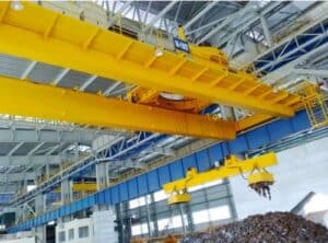
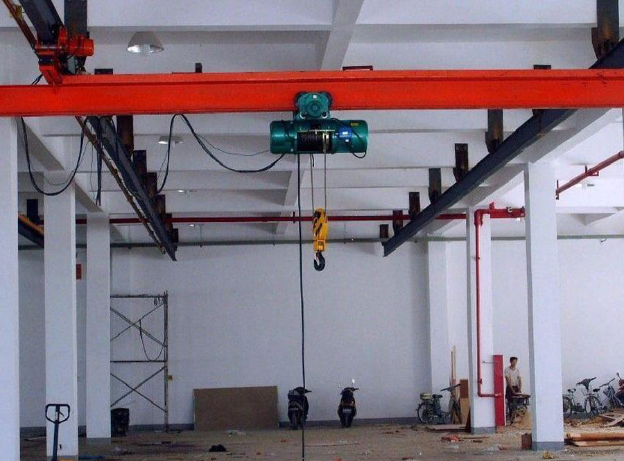
1. Box structure bridging
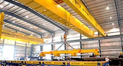
The box structure bridge is composed of main beams, end beams (also called cross beams), walking platforms and protective poles. The main beam and end beam are both box-shaped cross-section structures made of steel plates, so they are called box-shaped structures.
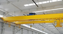
The end beam of the bridge crane is also called the cross beam. It is connected to the main beam by welding to form a bridge. It is also a box-shaped structure made of steel plates. Each end beam is made into two halves that can be divided into two halves, which are rigidly welded to the two ends of the main beam to form an “I” shape. , and then the two “I”-shaped bodies are connected with connecting plates and shear bolts to form the main frame-shaped bridge structure. The end beam is installed with the cart’s driving wheel set and driven wheel set, as well as protective railings, cart buffers and limiters, etc.
2. Truss structure bridge
According to the different cross-sectional forms of the main beams, the main beams of the truss structure have light weight and high stiffness. Especially in the case of small lifting capacity and large span, it shows its advantages. The truss structure has good dynamic rigidity and is lighter in weight than the box structure. However, compared with the main beams of box structures, the main beams of truss structures require more manufacturing hours, have larger dimensions, and have lower fatigue strength. Therefore, box-type structure main beams are still widely used in top manufacturers underhung overhead crane, while truss structure main beams are rarely used.
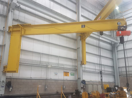
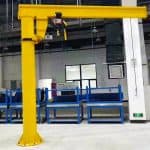
3. Gantry crane bridge
Gantry crane bridges also have box structures and truss structures. There are two types of main beams: double main beams and single and double beams. There are three common forms of outriggers: L-shaped, C-shaped and figure-eight.
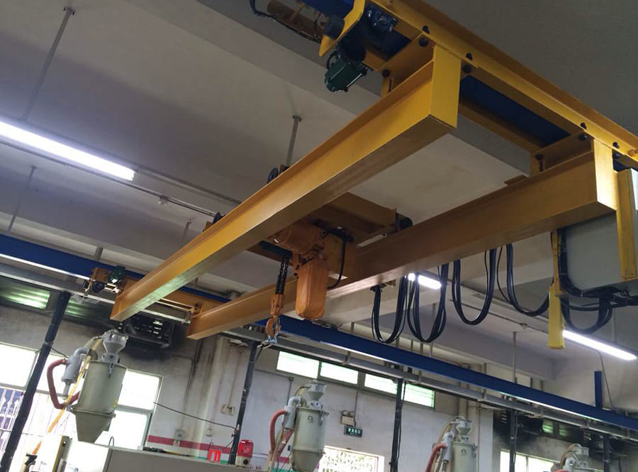
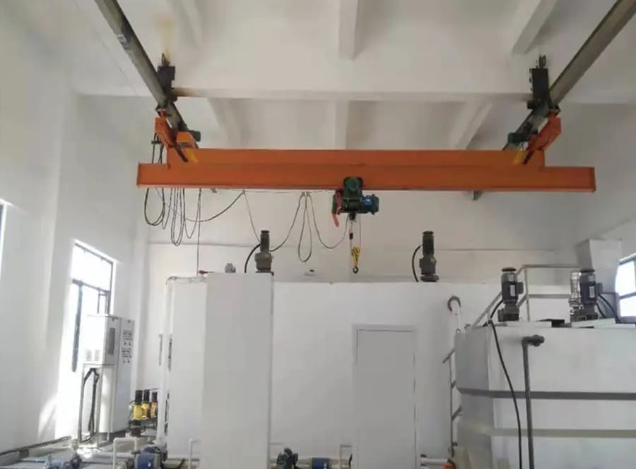
2. Small frame
The trolley frame is a box-shaped beam with the upper part made of steel plate and the lower part made of section steel or steel plate welded. A lifting mechanism and a trolley operating mechanism are installed on it. In addition, the upper part of the trolley frame is also equipped with a railing of no less than 1m. For cranes operating in the open air, the upper part of the trolley frame is also equipped with a rain cover. A double-hook trolley has two sets of upper lifting mechanisms. The lower part of the small frame is equipped with a striker and a buffer.
The arrangement of various mechanisms on the trolley frame is required to be compact, and the lifting machinery should be arranged in the middle as much as possible so that after lifting heavy objects, the forces on each wheel will be even.
3. Driver’s cab
As the name suggests, the driver’s cab is a place for crane operators to operate. It is generally located at both ends or in the middle of the crane’s bridge frame.
There are the following requirements for the setting of the bridge crane cab:
1. The connection between the cab and the suspension or supporting part must be firm, and its top should be able to withstand a static load of 2.5kN/m2.
2. Cranes working in high temperature, dusty, toxic and other environments should use a closed driver’s cab; the driver’s cab of a heavy duty underhung overhead crane working in the open air should have windproof, rainproof and sunproof facilities.
3. The driver’s cab should be located on the side without conductive trolley lines. If it must be located on the side with conductive trolley lines due to limited conditions, a reliable guard against electric shock should be installed.
4. Cranes whose working environment temperature is higher than 35 degrees and those that work at high temperatures, such as metallurgical cranes, should be equipped with a cooling device in the cab; those with a working temperature below 5 degrees should be equipped with a safe and reliable heating device.
5. The driver’s cab should have a good view to facilitate operation and maintenance; the operator’s cab should ensure that operators can evacuate safely and quickly in the event of an accident; the bottom of the driver’s cab should be paved with insulation templates or rubber and other insulating materials.
4. Auxiliary settings
In order to ensure the operation of the crane and personal safety, and to facilitate the work of operators and maintenance personnel, the following devices are also installed on the bridge crane.
1. Walking platform, on the outside of the two main beams, the walking platform close to the transmission beam becomes the transmission walking platform, on which the trolley operating mechanism and electrical equipment such as control panels, protection cabinets, resistors, etc. are installed. The walking platform close to the conductive beam is called Conductive walking platform, on which are installed electric pillars and trolley conductive sliding contact lines or cable brackets, conductive cables, etc. The walking platform should be made of corrugated steel plates with good anti-slip properties.
2. Protective railings. For safety, protective railings are installed on the end beams and outside of the two walkways. The height of the protective railings should not be less than 1050mm, and horizontal crossbars with a spacing of 350mm should be provided. The bottom of the protective railing should be equipped with a maintenance plate with a height of less than 70mm. Any part of the protective railing can withstand a load of 1kn from any direction without plastic deformation.