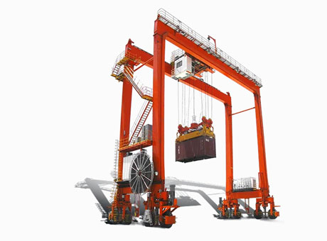
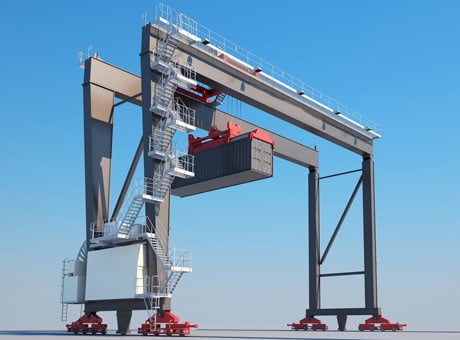
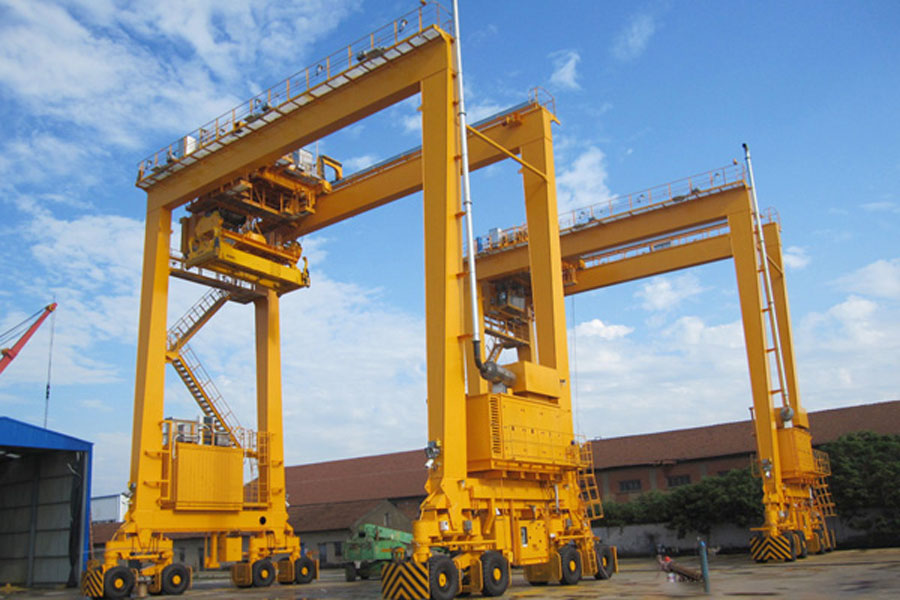
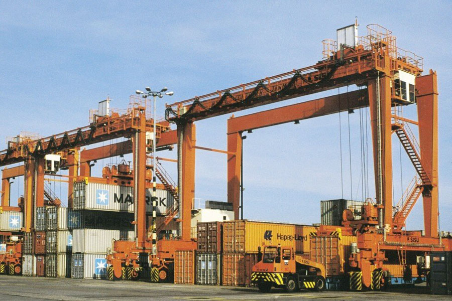
In SEVENCRANE automated rubber tyred gantry cranes, the positioning technology of hoist and hoist trolleys is a very important content. Under normal circumstances, the operation of large and small trucks of container gantry cranes is automatically completed by relying on positioning technology. The controller only needs to operate the equipment. The situation can be monitored by video. Unlike the final stage of the lifting operation, which requires human intervention, the automation of large and small vehicle positioning requires higher technical reliability and accuracy.
Cart Positioning Technology
The cart positioning technology of industrial automated rubber tyred gantry crane currently used is mainly a composite positioning technology, which is generally implemented through two sets of systems. Usually, one system is responsible for tracking positioning, and the other system is responsible for position positioning. The function of the tracking and positioning system is to identify the direction in which the cart is running and to roughly locate the position; the function of the position positioning system is to accurately identify the target position that the cart needs to reach. Due to different positioning technologies, there are many differences in their implementation details. The following types of cart positioning technologies have been put into use:
Cart encoder and signal mark composite positioning technology
This is a relatively common large vehicle positioning technology of heavy duty automated rubber tyred gantry crane. This composite positioning technology uses a cart encoder for continuous tracking positioning. The cart encoder is divided into incremental type and absolute value type. It is used as tracking positioning. The information that the encoder needs to feed back to the system is the movement of the cart. direction and a rough measure of the distance traveled in that direction. Since the measurement of walking distance is a rough positioning, it is theoretically possible to use both incremental and absolute encoders. Considering the accuracy of rough positioning, relatively accurate absolute encoders are generally used. In fact, due to factors such as the sliding of the cart wheels on the track and the accumulation of errors in the encoder, the position information provided by the encoder is still inaccurate.
Signal markers are used as a means of locating the bay level and are generally set on the center line of the bay level. There are many ways to implement it, including Hall magnets, magnetic nails with RFID, and other RFID devices. Its function is to accurately indicate the position of the bay position through the interaction between the signal mark and the signal mark reading device, and at the same time correct the encoder. This solution needs to rely on the absolute value encoder of the cart to identify the position of the cart. When the cart approaches the magnetic nail, the device is controlled to slow down so that the device can stop at the target position more accurately. If the encoder fails, there may be problems such as missed magnetic nails or large errors in the positioning of the cart. In order to avoid related problems, a FLAG signal can be added between the magnetic nails. This signal is realized through the baffle and photosensitive device. Its main purpose is to increase the encoder correction frequency to avoid the encoder’s response. error. Actual test results show that the positioning accuracy of the cart can be effectively improved. The combined positioning technology of the cart encoder and the signal mark has two limitations. First, the cart encoder relies heavily on the sliding of the cart wheel contact surface and cannot reflect the offset on both sides of the cart; second, the position of the signal mark is often It is fixed. Therefore, this composite positioning technology can only be used in track cranes and cannot be applied to tire cranes.
Composite positioning technology of path coding and position markers
This technology is applied in the automated rubber tyred gantry crane for sale renovation project. Path coding is a pseudo-continuous coding of the entire running path in a certain way. The coding is read through the coding recognizer set on the device to obtain running information such as running direction, speed and distance. This kind of coding is often discrete, but the coding density is high, so it can achieve an effect similar to continuous coding. Because the equipment runs fast, the recognition window of the code recognizer is generally larger, so that advance recognition can be achieved during the recognition process, that is, multiple discrete codes will appear in one recognition window, and the location and location of the device can be identified at the same time. All codes within a certain distance before and after improve the efficiency and error tolerance of code recognition, but sacrifice the accuracy of positioning. Therefore, bay mark is needed as a means of accurately positioning the equipment in the bay area. There are various forms of shell mark, and the requirements are that the mark recognizer has a narrow recognition window and accurate positioning. When the device runs to the bay mark, the mark recognizer emits a beam of light on the reflective plate, and this bright light point will be captured by the mark recognizer. In this way, the bay position is accurately positioned.
Satellite positioning and image recognition composite positioning technology
The most representative satellite positioning technology is GPS technology, which calculates the location of the receiver through the interaction between the GPS receiver and the navigation satellite. This positioning method has the advantages of all-weather, all-time, all-round and so on. It has little dependence on equipment and other facilities and can be applied to various container gantry cranes. However, high-precision GPS positioning equipment is expensive, and the accuracy of civilian GPS positioning technology is about 10 m. Therefore, satellite positioning technology represented by GPS can well complete the operation positioning of equipment, but it is not suitable for accurate positioning in bay areas. Image recognition technology uses a camera mounted on the device to capture the ground bay number mark, and calculates the precise position of the device relative to the target bay by analyzing the image. Theoretically, image recognition technology can complete operational positioning and position positioning. In fact, in locations without special markers, image recognition accuracy is low, takes up a lot of system resources, and the effect is not ideal. Therefore, satellite positioning is faster and more reliable for operational positioning. .
Satellite positioning and bayonet coding composite positioning technology
This technology is a modification of image recognition technology. The signal recognized by image recognition technology is a natural image signal, that is, a shell number mark set on the ground. Its characteristic is that it has almost no requirements for the standardization of natural image signals. However, this also makes image recognition more difficult and requires system resources. Requirements increase. In addition, the reliability of image recognition technology is seriously reduced when dealing with severely stained images and working in environments with poor lighting and visibility. Bayi coding is actually a standardized coding of original natural images, such as barcode marks, black and white square marks, QR code marks, etc. This standardized coding has high recognition efficiency and consumes less system resources. In addition, the coding itself Rule error tolerance, general defacement and occlusion will not affect recognition. If the code is placed at a reasonable location, the impact of light and weather on technical identification can be effectively avoided. Therefore, this technology simplifies image recognition technology and is more reliable than image recognition technology.

Car Positioning Technology
The operating mechanism of the container gantry crane trolley is different from that of ordinary bridge gantry cranes. It adopts a forced drive method, that is, driven by a rack and pinion or a chain and sprocket. The trolley will not slip during operation. At the same time, The trolley always runs along the fixed track, so the positioning method of the trolley operation is simpler than that of the trolley. A similar solution is more reliable and accurate when applied to the trolley positioning. Common car positioning methods include the following:
Dual laser ranging and positioning: Install the laser ranging device on the trolley frame, use the land and sea side stops as the ranging targets, and determine the running position of the trolley by calculating the distance relative to the stops. The two ranging devices of dual laser ranging calibrate each other, which is a redundant car positioning method.
Gray busbar positioning, also known as coded cable technology, is so named because the coding method uses Gray code. It transmits the information code on the Gray bus core to the induction loop through electrical coupling, and then decodes and identifies the information code through the information detection unit. Gray busbars are mostly used in the positioning of coke oven locomotives in steel plants, and were later introduced into the positioning of container cranes in ports. Its positioning accuracy can reach 5 mm.
The combined positioning of laser ranging and encoder is the positioning method with minimal changes to the entire machine. Generally, the container gantry crane is equipped with a trolley running encoder in the factory configuration. Since the container gantry crane is forcedly driven, the trolley encoder will be relatively accurate in determining the trolley position unless the encoder connection shaft is faulty. Adding a laser ranging device to calibrate the encoder can achieve better accuracy and reliability. This is also a redundant positioning method.

