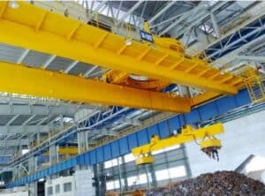
Safety requirements for main components of industrial wire rope hoist
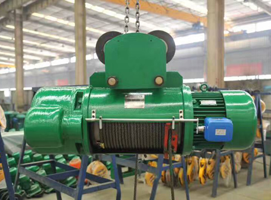
1. Lifting motor
(1) The motor type, basic parameters, performance and size should comply with the design of the product and the use requirements of the host.
(2) The protection level of the motor shell should not be lower than P44 (except for the wind cover).
(3) The locked-rotor torque, maximum torque and locked-rotor current of the motor at rated voltage should comply with regulations.
(4) The lead wires of the motor should have phase sequence marks. There should be a grounding screw at the junction box of the motor, and a grounding mark should be set near the grounding screw. This mark should be ensured to be clear at all times during the service life of the motor.
(5) Each fastening bolt of the motor should have anti-loosening measures.
(6) The braking of the motor should be smooth and reliable, and the static braking torque should meet the design requirements.
2. Lifting hook
(1) The appropriate lifting hook should be selected based on the rated lifting capacity of the industrial wire rope hoist manufacturer, the working level of the mechanism and the strength level of the hook.
(2) The mechanical properties of the lifting hook should comply with the provisions of GB/T10051.1 “Lifting Hook Part 1: Mechanical Properties, Lifting Weight, Stress and Materials”.
(3) The rated lifting capacity should be marked on the eye-catching place of the hook group, and a hook locking device should be installed. Electric hoists used for lifting molten metal should not be equipped with locking devices.
(4) The use of forged hooks on sevencrane industrial wire rope hoist factory should comply with the provisions of GB/T10051.2 “Lifting Hooks Part 2: Technical Conditions for Forged Hooks”. The surface of the hook should be smooth and clean, and should not have cracks, folds and other defects. There should be no cracks, white spots or other defects inside the hook that would affect the safety of use. Welding repair is not allowed for defects on the hook.
(5) Lifting hooks should be inspected before and during use. The inspection of forged hooks should comply with the provisions of GB/T 10051.3 “Lifting Hooks Part 3: Inspection of Use of Forged Hooks”.
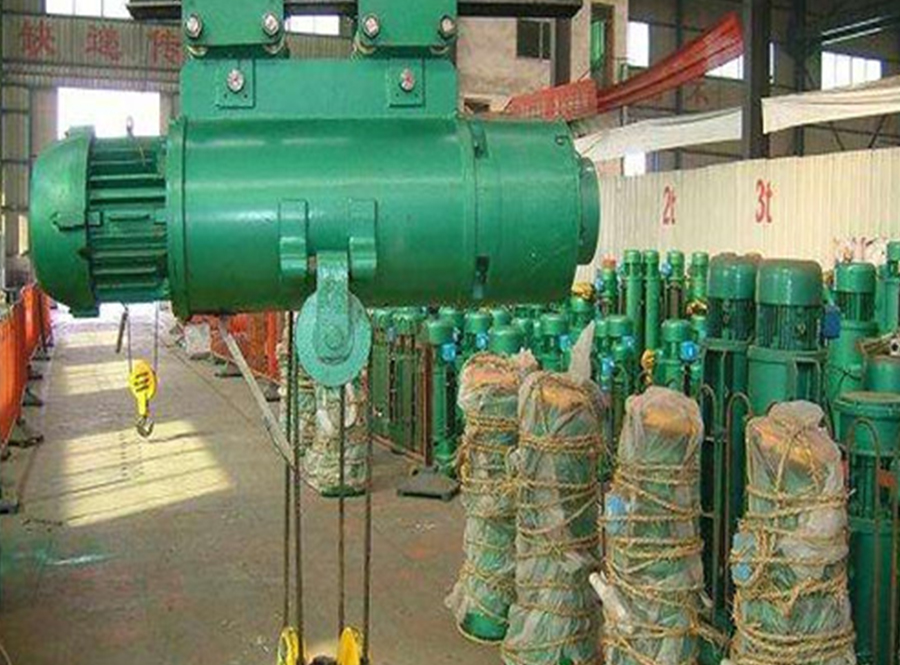
3. Wire rope
(1) The steel wireless remote control industrial wire rope hoist company should comply with the requirements of GB/T20118 “General Purpose Steel Wire Rope”. Line contact type steel wire ropes are preferred, and the nominal tensile strength is not less than 1570MPa. When electric hoists lift molten metal, high-temperature resistant steel wire ropes with metal rope cores or metal strand cores whose performance is not lower than that specified in GB8918 “Important Purpose Steel Wire Ropes” should be used.
(2) When the hook drops to the lowest limit position, the remaining safety circles of the wire rope on the drum (excluding the number of turns for fixing the rope tail) should be maintained for at least 2 turns. Under this safety circle, the rope end fixing device should not deform causing loosening when it withstands 2.5 times the maximum working static tension force of the wire rope.
(3) The use and maintenance of electric hoist wire ropes should comply with the regulations of GB/T 29086 “Safe Use and Maintenance of Steel Wire Ropes”.
(4) The end of the wire rope should be reliably fixed. When a wedge joint is used, more than 200mm should be left after the fixed end of the wire rope passes through the wedge. The remaining wires at the end of the rope head should not be loose and spread out. Use thin and soft iron wire to tighten the loose split parts. The tightening length is the diameter of the wire rope. More than 4 times. When a rope clamp is used for fixing, the rope clamp should be selected according to the nominal diameter of the wire rope. The place where the wire rope is clamped should be smooth, flat, and free of burrs. The installation of the rope clamp should meet the following requirements:
a) The number of rope clamps should meet the requirements: Table. Number of wire rope clamps b) When installing the wire rope clamps, the clamp base should be buckled on the working section (long side) of the wire rope, and the U-shaped bolt should be buckled on the tail section of the wire rope. c) Wire rope clamps shall not be arranged alternately on the wire rope. d) The distance between the wire rope clamps is equal to 6 to 7 times the diameter of the wire rope, and the length from the rope head to the last rope clamp is not less than 14 times the diameter of the wire rope.
(5) The wire rope fixings should be inspected regularly to check the deformation, wear, cracks and slippage of the detachable wedge joint or rope clamp itself, as well as the broken wires and corrosion inside the device and the rope end to ensure Tightening reliability of rope end fixation. If there is obvious broken wire or corrosion near or in the rope end fixing device, the wire rope can be shortened and reinstalled on the rope end fixing device, and the length of the wire rope should be enough to meet the requirements of the reel when the hook is at the lower limit. The number of winding turns (2 turns) required.
4. Pulley
Cast iron pulleys should not be used on electric hoists for lifting molten metal.
5. Rope guide
(1) The best industrial wire rope hoist for sale should be equipped with a rope guide or take other measures to prevent rope chaos.
(2) When using a rope guide, it should be ensured that when the hook is lowered and there is no other external force acting on the wire rope, the wire rope can still be discharged freely from the rope outlet of the rope guide. When lifting and lowering the rated load, the deflection angle of the wire rope to the vertical plane of the drum axis is ±3°, it can still work normally.
(3) When the rope guide is used in conjunction with the lifting limiter, it should be able to ensure a reliable limiting effect.
(4) The rope guide is a consumable part and should be inspected and maintained regularly. If it is found to be worn, it should be replaced in time.
6. Electronic control equipment
(1) The transmission control scheme of the electric hoist’s electronic control equipment should include the following necessary protection links:
——Emergency power-off switch (emergency stop switch should be red and cannot reset automatically); ——Ground protection; ——Loss of voltage protection; ——When wrong phase and lack of phase will cause danger, wrong phase and lack of phase should be set Phase protection; – The contactor that controls the forward and reverse rotation of the motor should be electrically interlocked and should be equipped with a mechanical interlocking device. If necessary, mechanical interlocking can also be added to the button.
(2) The structural design of the electronic control equipment should meet the requirements for the use of electric hoists, and the protection level of its shell should not be lower than IP44. For electrical components installed in P44 shells, the protection level is generally IP00.
(3) The lifting motor should have one or more of the following protection functions, and the specific selection should be determined according to the motor and its control method:
——For instantaneous or inverse time action overcurrent protection, the instantaneous operating current setting value should be approximately 1.25 times the maximum current of the motor; 1. Set thermal sensing elements in the motor; ——Thermal overload protection.
(4) The surface of the shell of the electronic control equipment should be smooth, with no obvious burrs, cracks, etc. on the edges. If the shell needs to be painted, the surface color after painting should be uniform and firmly adhered, and there should be no wrinkles, flow marks, bubbles, etc.
(5) Electronic control equipment should be firmly fixed, and the surfaces of all ferrous metal components, accessories, fasteners, etc. should be protected against rust.
(6) The button operation direction of the button device should be consistent with the action direction of the electric hoist.
(7) The cable inlet of the button device should have a rubber sleeve to protect the cable and measures to compress the cable.
(8) The button action of the button device should be flexible, the contacts should be in good contact, and the overall structure should be free of defects.
(9) The grounding screw of the grounding device of the electronic control equipment should not be smaller than M6, and there should be an obvious grounding mark.
(10) All wires should be firmly marked consistent with the circuit diagram (or wiring diagram);
(11) The inlet and outlet of the electronic control equipment shell should have sheaths to protect the wires and cables;
(12) For electric hoists that use multiple operating modes, there should be interlocking protection to ensure that only one operating mode can be effective at the same time.
(13) When using a suspended control device, the control circuit voltage of the button device should not exceed the 50V safety voltage. All control buttons that directly control the actions of each mechanism should be self-resetting to ensure that the electric hoist is in a stopped state when no one is operating it.
(14) When using a suspended control device, effective suspension load-bearing measures should be taken for the connecting cable of the device.
(15) Electric hoists that lift molten metal should use remote control or non-following control methods away from heat sources, and protective measures should be taken for motors and electrical equipment.
(16) The button device should be equipped with an emergency stop switch, which should be able to cut off the power supply in case of emergency.
(17) The insulation resistance of the electric hoist should not be less than 1MΩ.
(18) The resistance value of the electric hoist’s ground connection should not be greater than 0.1Ω.

