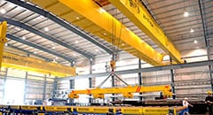
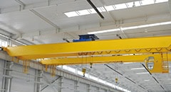
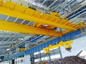
The kaksipalkkinen siltanosturi has superior performance, compact structure, light weight, reliability and operation, and can meet various working conditions. It can reduce the overall investment in the factory, improve production efficiency, reduce maintenance costs, and save operating energy consumption.
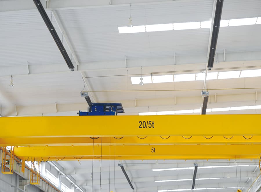
1. Structure of double-girder bridge crane
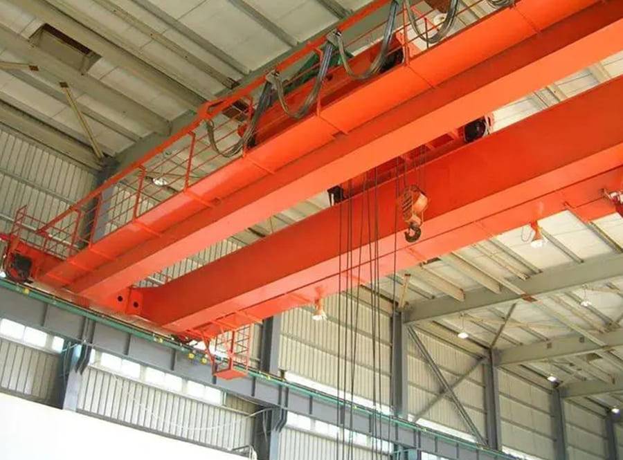
1. Bridge: It consists of two main beams, two end beams, walking platforms, guardrails and other components. There are two structural forms: box-shaped and truss;
2. Cart operating mechanism: It is composed of motor, brake, reducer, coupling, transmission shaft, angle bearing box, wheels and other parts;
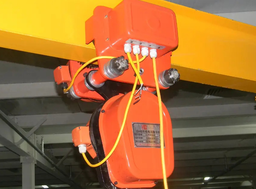
3. Lifting trolley: It consists of a trolley frame, a lifting mechanism and a trolley operating mechanism;
4. The lifting mechanism is composed of motors, brakes, transmission shafts, couplings, reducers, drums, fixed pulleys, wire ropes and other components. Divided into single brake and double brake;
5. Cab: Where the crane operator works. It is equipped with control equipment (linkage table or cam controller), power distribution protection box, signaling device and lighting equipment. The crane can only be started after the hatch is closed. This can avoid personal accidents caused by someone working in the car or driving before someone enters the driver’s cab. 2. Transmission principle of double-girder bridge crane The movement of the general-purpose bridge crane is composed of three movements: the longitudinal movement of the cart, the transverse movement of the trolley, and the up and down movements of the hook.
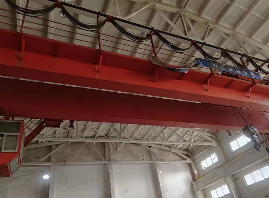
2. Transmission principle of industrial double girder overhead crane
1. Transmission of the lifting system: The power source of the lifting mechanism is generated by the electric motor. Through the gear coupling, compensation shaft, and brake wheel coupling, the power is transmitted to the high-speed shaft end of the reducer and decelerated. After the high-speed motor is reduced to the required speed by the reducer, the low-speed shaft of the reducer is output, and the power is transmitted to the drum set through the internal ring gear on the drum, and then the hook is raised and lowered through the wire rope and pulley set. , thereby completing the purpose of lifting and lowering heavy objects;
2. Transmission of the lifting trolley operating system: The power is generated by the motor, and is transmitted to the high-speed shaft end of the vertical three-stage reducer through the brake wheel coupling, compensation shaft, and half-tooth coupling, and is passed through the vertical three-stage reducer. After the three-stage reducer reduces the high speed of the motor to the required speed, it is output by the low-speed shaft of the reducer, and is connected to the car’s driving wheel shaft through a half-tooth coupling, a compensation shaft, and a half-tooth coupling. This drives the rotation of the trolley’s driving wheels and accomplishes the purpose of the trolley’s transverse transportation of heavy objects;
3. Transmission of the trolley operating system: The power is generated by the motor, and is transmitted to the high-speed shaft end of the reducer through the brake wheel coupling, compensation shaft and half-tooth coupling, and the high-speed rotation of the top manufacturer double girder overhead crane is transmitted through the reducer. After the speed is reduced to the required number of revolutions, it is output by the low-speed shaft of the reducer and connected to the driving wheel shaft of the cart through a full-tooth coupling, thereby driving the rotation of the driving wheel of the cart and completing the purpose of lifting heavy objects longitudinally on the bridge. . The driving mechanisms at both ends of the cart are the same.

